The Real-World Resolution Requirements
I was not sure what to call this article. I first thought it should be titled, “Why The Johnson Criteria is Wrong.” We use this criterion to predict how far away we can see something using a specific camera and lens. The criteria define the threshold for detection, recognition, and identification (DRI). The industry has used this criterion since World War II. It has not been updated to reflect today’s technology and resolution requirements.
Better criteria can help us select the right long-range camera for an application. It can be used to predict the working distance of long-range thermal and optical camera systems.
What Affects the Details of What We Can See
The number of pixels required for detection, recognition, and identification will determine the working distance of a specific camera. To review, in the 1950s John Johnson defined a criterion for visual thresholds using image intensifiers cameras. His criteria were based on line-pairs because the imaging equipment used a scanning system that was like the original TV system. He used volunteer observers to define the minimum resolution for detection, orientation, recognition, and identification. The volunteers could identify these benchmarks only 50% of the time. That is why it was defined as threshold measurements. Today we would like a method for specifying the range of a camera that will work all the time, not something that works 50% of the time. If we do not use the Johnson criteria, then what should we use? This article describes better criteria for today’s surveillance and security camera systems.
Various parts of an IP camera contribute to the visual performance of the system. We must consider not only the sensor, but also the lens, camera sensor, amplifier, the mounting system, and the mechanism that moves the camera view up and down (the Pan, Tilt mechanism). Look at our article, Understanding IP Camera Specifications, What’s Important, for more about the camera system.
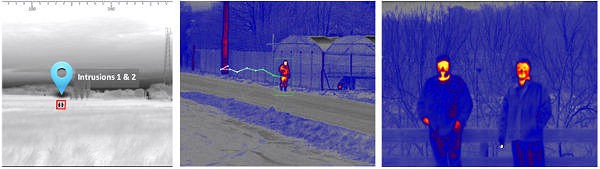
Both the thermal camera and the optical camera have similar components, but each provides a different type of images. This means the resolution required to see something could be different in some situations. For example, a thermal camera may be able to pick up a hot (relative to the background) object better than an optical camera. The higher energy from the heated object will cause the image to bloom, and appear much brighter than the equivalent view from an optical camera. The optical camera is much better at identifying objects because it provides better contrast and color than a thermal image.
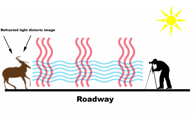
The environment affects how well we can see. It could be very windy, or dark, or there could be fog or other atmospheric problems. The further away we try to see something the more atmospheric conditions affect performance. For example, heat waves can distort the image enough so we cannot recognize the object. The suggested criteria try to take into account all these factors.
Calculating the New Standard for Resolution
We use the pixel resolution to determine what we can see. Take a look at our article, What IP Camera Resolution Do You Need. The more pixels required, the shorter the actual distance to a target.
The Johnson criteria state the following thresholds that are achieved 50% of the time:
- Detection: We need 1.0 +/− 0.25 line pairs to detect an object 50% of the time.
- Recognition: The type object can be discerned, a person versus a car (4 +/− 0.8 line pairs)
- Identification: A specific object can be discerned, a woman versus a man, the specific car (6.4 +/− 1.5 line pairs)
The new criteria should provide enough information so that we achieve 100% detection, recognition, or identification. The first thing we need to do is convert line-pairs to pixels.
Converting Line Pair to Pixels
How many line pairs do we need to detect something 100% of the time? First, let’s convert line pairs to pixels because the resolution of today’s cameras is specified in pixels rather than lines.
Line pair resolution is defined as at least one black and one white detection. Theoretically, you could have one pixel per line, but in reality, it requires more than 2 pixels. We need at least one pixel that detects black, a second that detects white, and a third that detects another black. At a minimum, we need at least 3 pixels to detect a small white object. However, there’s more to this. We need to take into account a certain amount of statistical uncertainty of a sensor picking up the signal.
The Kell Factor
In the real world of detection, the white spot could appear somewhere in between the pixels of the sensor. This means we need more pixels to actually detect the small object. The concept of the uncertainty of where an object appears on a sensor was introduced in 1934 by Raymond Kell. It was first applied to sampling an image to avoid beat frequencies affecting the image. The Kell factor is a fudge factor that attempts to adjust for the uncertainty of analog sensors. The number has changed depending on how it is used. Kell said the number should be 0.64, but today people usually use 0.7.
The Kell factor increases the number of pixels required. We adjust the pixels using the formula: pixels/kell factor
3 / 0.7 = 4.29 vertical pixels.
The Mesnik Factors
Besides the Kell factor, there are other real-world factors that can affect what we see. For example, long-range lenses sometimes do not have the clarity they require to accommodate the higher resolution sensors. Other factors include low-light operation and atmospheric conditions that affect visibility.
The atmospheric conditions can be very obvious like rain or fog or can be subtle like heat waves or higher humidity. The view can be reduced dramatically by fog, haze (smoke), rain, or snow. Unfortunately, the amount of reduced vision can vary depending on the intensity of fog or rain. Thermal cameras can see through fog and haze while optical cameras can not. Some optical cameras include fog filters. This can help in some situations. Less obvious conditions such as higher humidity can reduce visibility because it reduces contrast. The further away an object is, the more light scattering occurs.
Long range cameras must also be mounted to very stable platforms. Placing a camera on top of a tower can cause vibration that affects the clarity of the video. Some long-range cameras include image stabilization. There are electronic and mechanical mechanisms for stabilizing the cameras.
We can adjust for some of these real-world visual problems. We have come up with the following factors that result in the need for increased pixel count for meeting the visual criteria.
Lens factor: from 1 to 0.6 depending on the actual lens clarity selected
Low light noise factor: When there are low light conditions, the amplifiers in optical cameras can introduce noise as they try to amplify the available light. Thermal cameras are not affected by this. However, thermal cameras are affected by the difference in temperature between the object and the background. The factor for low light conditions using optical cameras varies from 0.9 to 0.6 depending on the noise introduced by specific camera amplifiers.
Atmospheric Factors: heat waves and other clear day factors such as humidity increase with distance.
Atmospheric Distance Factor. These are all estimates of atmospheric effects on visibility. Actual visibility is affected by the difference in contrast between the object and the background.
- For distance less than 1000 m (0.62 miles) = 1.0
- for distance between 1001m – 2000 m (1.24 miles) = 0.9,
- for distance 2001m to 3000 m (1.86 miles) = 0.85,
- for distance over 3001 m to 5000 m = 0.8
- for distance 5,001 m to 10,000 m = 0.75
- for distance 10,001 m (6.2 miles) to 15000 m (9.3 miles) = 0.7
- for distance 15001m to 20000 m (12.4 miles) = 0.65
In reality, the earth’s curvature limits how far away we can actually see something. A camera that’s mounted 6 ft. above the ground has a maximum visibility of about 4700 m (2.9 miles). If the same camera is mounted on top of a 100 ft. tower, it can see 19600 m (12.2 miles)
In general, the more you pay for a specific camera system, the higher these numbers are and the clearer the image will be. For example, you pay more for better optics, cameras with better low light capability and low noise, cameras with fog filters, and those with more stable pan and tilt mechanisms.
An example of using the factors:
The following example is a camera system used at night, that will observe objects about 2-miles away. We excluded severe atmospheric conditions such as fog that could reduce visibility dramatically. We calculated the pixel counts for an optical camera and a thermal camera with similar lens magnification.
- Reasonably good lens (costs a lot) = 0.9
- Used at night: = 0.75 for optical, 1.0 for thermal camera
- Distance = 3219 m (2 miles) = 0.8
- Total for Optical camera = 9 x 0.75 x 0.8 = 0.54
- Total for Thermal = 0.9 x 1.0 x 0.8 = 0.72
- Optical Camera Adjustment to the pixels required = Pixels / Mesnik factors = 4.29 / 0.54 = 7.9 pixels (round up to 8 pixels)
- Total Pixels for Thermal Camera = 4.29 / 0.72 = 5.96 pixels
The fewer pixels required, the further away we can see. In this example, we need more pixels for the optical camera than for the thermal camera. This means we can see further at night using a thermal camera than using the optical camera.
The New Standard Criteria
Here’s the summary of the new DRI standard.
Detection: 8 vertical pixels across the target
Recognition: We calculated we require eight times the 4 line pairs or 32 vertical pixels across the target
Identification: We calculated we need eight times the 8 line pairs = 64 vertical pixels across the target
Note that these are all vertical pixel counts so that we can be consistent with the original Johnson criteria. We generally use the horizontal pixel counts to calculate the field of view. Since the pixels are square, we can use the same definitions for our field of view calculations.
Summary
The Johnson Criteria is outdated. It does not provide the right measure of resolution for today’s camera systems. We need a better way to define the information required to calculate the expected camera performance. The new criteria provide a better estimate of the pixels required to achieve our performance objectives. The calculations reduce the expected distance for thermal and optical cameras but provide a much more realistic prediction of actual performance. For more about predicting what you can see, look at the article Calculating What You Can See with Your IP Camera
For help specifying the right IP camera system, please contact us at 800-431-1658 in the USA, or at 914-944-3425 everywhere else, or use our contact form.