Wiring the IP Reader-Controllers
The latest access control systems are much easier to install than the older systems. Of course, it’s only easy if you know exactly how to connect everything. The devil is in the details, and this article provides the wiring diagrams you need to make your access control system work.
As a review, the advantage of IP access control systems is that everything is located at the door. The following diagram shows an example of an IP access control system that uses a reader-controller.

The reader-controllers attach to the network and use PoE. They include a pigtail of wire that connect to the electric lock, the REX button, door sensors, and motions detectors. There are several configurations available, and they all use special software for access control management.
IP Reader-Controller Wiring to an Electric Strike
The following diagram shows an example that uses the Isonas reader-control in an indoor installation. The reader-controller is connected to a network switch that includes PoE. The pigtail on the back of the reader-controller provides all the connections to the strike, REX, motion detector, door open sensor, and any other equipment required at the door.
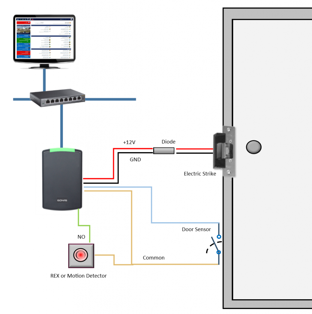
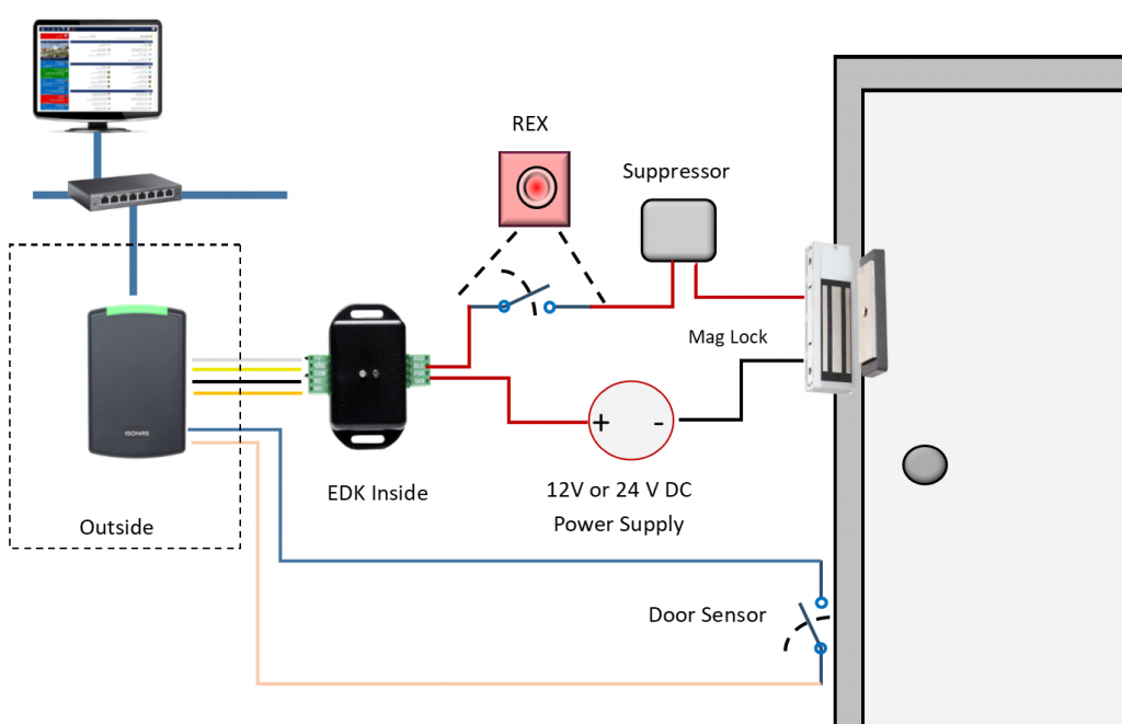
Power (12VDC) is available from the reader-controller. There is up to 500 ma of current available to drive an electric lock. If more power is required, the External Door Kit (EDK) is required. The voltage is applied to the electric lock, and the relay in the EDK controls the lock. The diagram below shows the wiring using an external power supply.
Reader-Controller and the External Door Kit
When the Isonas reader-controller is installed outside, the External Door Kit (EDK) is added to provide additional security. In this configuration, the reader-controller sends a coded message to the EDK located indoors. This prevents a vandal from shorting wires and unlocking the door from the outside. The EDK also contains a relay that can provide the power required by the magnetic lock. Magnetic locks require more power than the electric strike.
Door Access Control at the Door
The Hartmann, access control system, uses a different configuration. The system can be used with internal doors or external doors. In this system, there is a door reader outside the door, and a controller portion located inside the door. The controller connects to a network drop that includes PoE. This is a more flexible system since it can use many different types of door readers. This access control system can use a standard RFID reader that uses card credentials, or a smartphone door reader, a biometric door reader, or even one that recognizes faces and measures a person’s temperature.
Since the intelligent controller is located inside the door, it provides security against vandalism. The controller provides the 12V DC power for the electric strike.
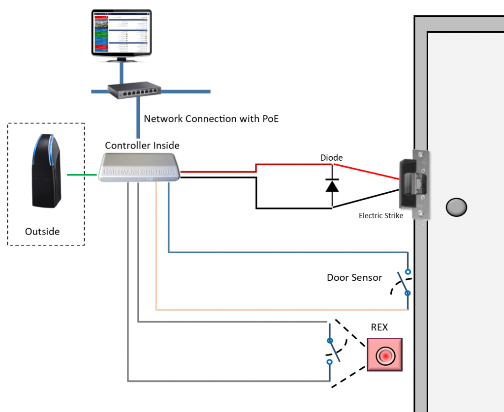
This system also supports the higher power required by maglocks. In this case, an additional 12 VDC or 24V DC power supply would be required. Maglocks also require a suppressor (not shown on the diagram) to prevent back EMF that could damage the relay.
Biometric Door Access Control Wiring Summary
Some biometric reader-controllers include a network interface as well as a Wiegand interface. The Wiegand interface allows you to attach the unit to a standard door access controller. Most of the biometric reader controllers require a separate power supply instead of using PoE. The following diagram shows how the face recognition panel is wired.
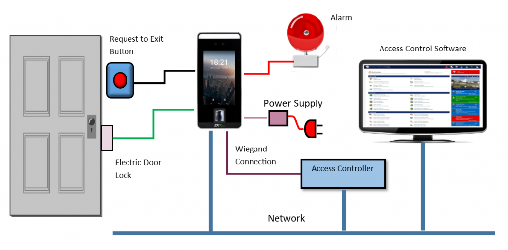
Some biometric readers can check the temperature of a person entering a secure area. These multi-function biometric panels can be used as standalone monitoring stations that scan body temperature and can also check if the person is wearing a mask.
Door Access Control Wiring Summary
Wiring an IP access control system is less complicated than the older centralized access controller systems. Rather than running wires from a central location, the IP access control systems make use of the network infrastructure. The intelligence is located at the door, so there a short runs of wire to the lock, REX, sensors, and other devices required for access control. There are reader-controllers and readers with separate controllers and some that can be powered using PoE.
If you need help selecting the right access control system, please contact us at 800-431-1658 in the USA, or 914-944-3425 everywhere else, or use our contact form.